| |
 |
|
| Therminal Full User Manual |
|
| Note: Examples of SMS commands to change settings or request information are highlighted.
Switch your browser's built-in translator to the original language of the page before copying the command to the clipboard. |
|
|
| Quick Start Guide |
|
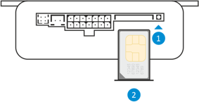
1. Press with a thin blunt object (phillips screwdriver, pen, etc.) on the SIM-holder ejector pushbutton, pull for the SIM-holder
and pull the holder out of the housing.
2. Put the SIM into the holder to commit and insert the holder back to the housing up to the stop.
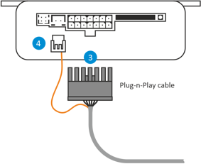
3. Connect Plug-and-Play cable to the module
4. Connect thermo sensor's orange wire of Plug-n-Play cable to the module
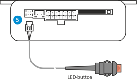
5. Connect LED-button
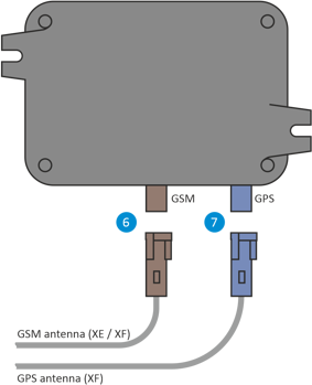
6. Connect external GSM antenna to the module
7. Connect external GPS antenna to the module (XF only)
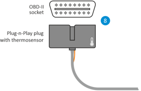
8. Find OBD-II service connector at the left lower point of the dashboard. Gently push the plug to the OBD-II connector.
9. Wait for network registration complete during 30 seconds (5 flashes in series by the LED-button)
10. Switch the ignition on for 30 seconds
| | |
|
Control via SMS does not require user's number registration on the modem. You can skip the following steps if you do not
plan to use apps or voice call to control the heater. Use the next commands to start and stop the heating:
1234 heater on
1234 heater off
The default common user password 1234 can be changed with the Set passwords command.
See also Control by SMS.
|
|
| | |
11. Press and hold LED-button until its embedded red LED indicator will flash from 10 to 14 times. Then release the button. LED indicator starts
to flash by series of 10 flashes.
12. During 3 minutes make voice call to GSM-module number and wait for busy tone.
Note: The number registration can take up to 5 minutes. Don’t make others voice calls and don’t send additional SMS on GSM-module
number. The procedure can’t be restarted without reset of GSM-module to factory settings.
13. If the registration is successful, GSM-module will send SMS:
NOTICE: registration successful, USERID: xxxxxxxxxxxxxxx, PASSWORD: xxxx
14. Store this message. Fields USERID (Driver identificator) and PASSWORD is used in Application Setup.
15. You can detach outer LED-button if you don’t want to install it. |
|
|
| Description |
|
Autoplugin Therminal is automotive climatic GSM-module intended for heater and ventilation remote control from mobile phone or smartphone. Voice call, SMS or
Android/iOS application may be used to access Therminal.
The applications use data transfer via proprietary secure internet server. In order to warm up the engine
and the interior Therminal can control fuel and electric heaters, to ventilate the interior — climatic module, to cool the interior — engine start module. |
|
|
| GSM-Module Possibilities |
|
| Remote control via Android/ iOs application via server and/or SMS. State of the art data
transfer protection methods for server connection. |
|
| Remote control via SMS with easy to remember commands |
|
| Simple remote control by using a voice call (incoming call acceptation, hanging up,
replying with SMS or data message, launching the preprogrammed function) |
| Parking heater remote control with feedback - informing about heating completion and
heating errors. |
|
| Possibility to control engine heating and interior heating separately |
|
| Possibility to use engine remote start to increase heating efficiency |
|
| Weekly and shift work schedules in the apps |
|
| Outer thermo sensor for interior temperature registering |
|
| Outer LED-button for one-touch control with programmable function: from the heater control
to emergency button |
|
| Approximate geoposition by GSM signals (all versions), accurate geoposition by GPS/GLONASS
signals (XF version only). |
|
| QiuckStart procedure for installation simplifying (installation "from the box"). It is
enough to send 1 SMS or make a voice call on modem number after SIM installation. |
|
| Fully functional multi-user mode for 3 registered users. The principle "only the driver
controls the vehicle". Notifications are sent to the user, who is the Driver at the moment, and don't disturb other users of the system. |
|
| Separation of user access to confidential information (i.e. to the vehicle location). |
|
| Accurate information of the heater operation including the source of the heater startup
or stop event. |
|
| Automatic application adjustment (auto configuration). After applying only functions
supported by the hardware remain available in the app. |
|
| Flexible adjustment of the device for different needs. Fully programmable inputs and outputs. |
|
| Power save modes allow the user don't remember how long the vehicle stay inactive during
the parking with Therminal connected. After the first inactivity period Therminal goes to the periodical operation mode, but after the second period finishing switches off all radio
modules, thus minimizing power consumption. |
|
| Algorithms of remote control for fuel fired parking heater, ventilation, engine start,
electrical parking heater of engine/interior. |
|
| GSM pager mode for the factory alarm system (alarm triggering notification) |
|
| The function of automatic heater operation time calculation based on weather forecast
for the region of the smartphone/vehicle location. |
|
|
|
| OBD-II Connection Description |
|
For cars listed below the module can be connected to the OBD-II service socket by the means of supplied Plug-n-play cable. All the time when
the socket is not used for the car diagnostics, Therminal can be connected to the socket for the operation. Therminal can be disconnected from the socket
anytime without need of further readjustment.
The Plug-n-Play connection is available for:
| Ford Focus 2004-2017 |
| Ford C-Max 2004-2018 |
| Ford Grand C-Max 2010-2018 |
| Ford Kuga 2008-2019 |
| Ford Connect 2014-2018 |
| Ford Mondeo 2007-2013 |
| Ford S-Max 2006-2015 |
| Ford Galaxy 2006-2015 |
| Ford Transit Custom 2013-2016 |
| Ford Tourneo Custom 2013-2016 |
| Ford Transit Van 2014-... |
| Volvo V40 / V40CC 2012-... |
| Volvo S60 2005-2018 |
| Volvo S80 2005-2016 |
| Volvo V60 2010-2018 |
| Volvo V70 2005-2016 |
| Volvo XC60 2008-2016 |
| Volvo XC70 2005-2016 |
| Volvo XC90 2005-2014 |
|
|
|
| Preparation for Work |
|
SIM-card in Mini-SIM format is required for GSM-module operation and should be purchased separately from local GSM operator (2G network with GPRS
technology support is demanded). If the operator supports 3G/4G phones only, a SIMcard from the operator can’t be used in Therminal.
Choose tariff plans
with non-expensive/pre-paid SMS traffic for control by SMS or with pre-paid mobile data traffic for control via Internet (50-100 Mb per month is enough). Combine phone account
with GSM module account if possible.
Install SIM card into the GSM-module, as shown at the figure. The operation should be performed with unplugged power
from the GSM-module. Press with a thin blunt object (phillips screwdriver, pen, etc.) on the SIM-holder ejector pushbutton (1), pull for the SIM-holder
and pull the holder out of the housing (2). Then put the SIM into the holder to commit (3) and insert the holder back to the housing up to
the stop (4).
It is necessary to make adjustments for some cars before the operation:
Ford Focus 2 (2004-2007), Ford C-Max (2003-2006):
Turn on the ignition and select in the driver information system menu:
Your settings > Aux.heater programming > Instant control > Auto
Ford Focus 2 (2008-2011), Ford C-Max (2007-2010), Kuga (2008-2012):
Start the engine and select in the driver information system menu:
Set > Menu > Settings > Auxiliary Heating > On > Off > On [again] |
|
|
| Sequencing |
|
Find the service socket in your car. It is a 16-contacts, double row socket. Usually it is placed at the left side of the dashboard, below the light control
switch. The socket can be covered by the enclosure or by the glove box.
Connect Plug-n-Play cable and the LED-button to the module. Connect orange wire of Plug-n-Play cable to the module. For Therminal-DXE/DXF versions connect external GSM-antenna into
the violet socket. Finally connect Plug-n-Play cable to the service socket.
Wait for network registration complete during 30 seconds (5 flashes in series by the LED-button), then switch the ignition on for 30 seconds.
Launch the Quickstart procedure (see Getting Started). When the procedure will be completed make a voice call on GSM-module number
and make sure the heater is started. You can detach outer button if you don’t want to install it.
Find space inside the dashboard for kit placement. Secure module and cables
inside the dashboard with straps. GSM module can be fixed with adhesive tape or can be fixed by straps. For Therminal-DXC version pay attention that internal antenna of GSM-module
(placed at the housing’s side, opposite to SIM-holder) doesn’t stay close to metal parts of the dashboard. For Therminal-DXE/DXF versions connect all antennas’ connectors to the
GSM-module, according to connectors’ colors. For Therminal-DXF the GPS/GLONASS antenna has a magnetic base which can be attached to metal parts. Or can be fixed with adhesive tape.
It is important to point the antenna toward the sky and don’t cover it by metal parts from the sky side.
GSM-module can indicate GSM signal level by the button-embedded LED.
This mode can be useful to find an appropriate location of the GSM-module (Therminal-DXC) or outer antenna (Therminal-DXE/DXF). To activate the mode press and hold the button until
the embedded LED flashes from 15 to 20 times, then release the button. The LED starts indicate GSM signal level by frequent flashes (1-5) in series. Signal status will be refreshed
every 10 seconds.
Before the final fixation of the module make sure that cables’ length is enough to make connection into OBD-II socket. Shorten excess length of the
Plug-n-Play cable by straps and fix all the cables of kit inside the dashboard. Finally connect Plug-n-Play cable to the OBD-II service socket. |
|
|
| Unplugging from the Service Socket |
|
| If the connector of Plug-n-Play cable has the strap for extraction, take the strap with your hand and slightly pull for the strap. Take the connector’s
housing by other hand and, moving the housing from side by side, gently extract the connector from the socket. If the strap is absent in connector’s design, take a flat non-shape
item and insert it to the connector’s slot placed on the narrow side of the connector. Then, using it as a lever, gently extract the connector from the socket. |
|
|
| Getting Started |
|
If you plan to control Therminal by typing SMS manually, go to the chapter Control by SMS.
For other control methods (voice call, iOS app or Android app via internet) it is necessary to perform a procedure called Quickstart. It is recommended to execute
Quickstart from the phone of main user (administrator). The procedure can be started in two ways:
1. Send SMS to GSM-module number: 1234 Quickstart
2. Press and hold GSM-module’s button until its embedded red LED indicator will flash from 10 to 14 times. Then release the button. LED indicator starts to flash by series of
10 flashes. During 3 minutes make voice call to GSM-module number and wait for busy tone.
Note: The number registration can take up to 5 minutes. Don’t make others voice calls and don’t send additional SMS on GSM-module
number. The procedure can’t be restarted without reset of GSM-module to factory settings.
If Quickstart is successful, GSM-module
will send SMS:
NOTICE: registration successful, USERID: xxxxxxxxxxxxxxx, PASSWORD: xxxx
Store this message. Fields USERID (Driver identificator) and PASSWORD is used in applications. If Quickstart is unsuccessful, such type of SMS will be received:
NOTICE: registration failed, GROUP: XXXXXXXXXXXXXXX, <GPRS and server settings>
In order to control the module from app via internet it is necessary to find and eliminate the fault reason. And then re-register GSM-module on
server (see Register command). If you plan to use only voice calls to control GSM-module, just switch off internet access
by command:
1234 Internet off
and go to chapter Control by voice call.
|
|
|
| Application Installation and Setup |
|
Use Google Play to install the application in Android OS. Use App Store in iOS. The application’s name for searching: Therminal
1. Open menu in the app: Settings > Vehicle access.
Fill in Driver identificator and Password fields.
2. In menu Settings > Application > Autosetup choose Apply.
Note: Autosetup procedure can take up to 3 minutes.
|
|
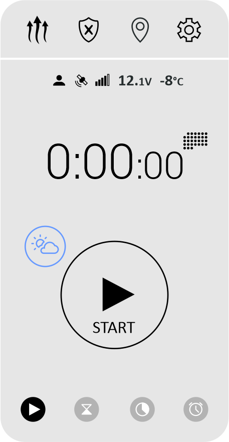
| Heater Control from Application |
|
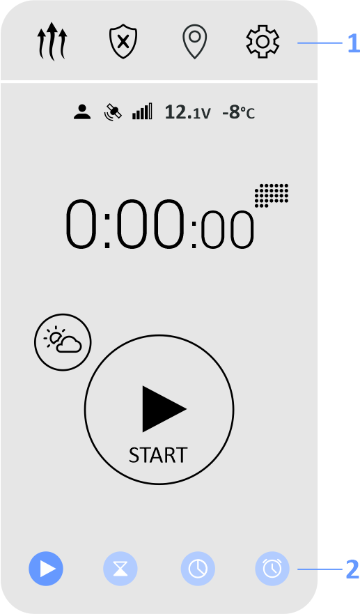
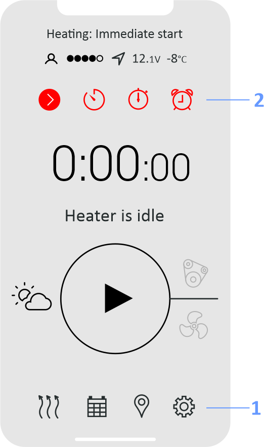
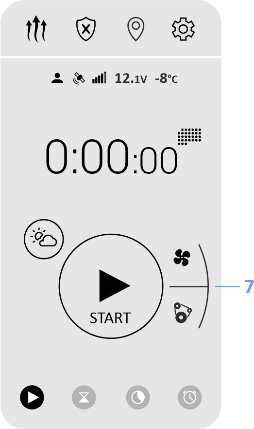
Open an application and select "Heating" section to have direct control for the heater. The Start/Stop on-screen button enables or disables selected mode of
heater control and confirms notifications.
 |
|
 |
|
1 — App sections
2 — Heating start modes |
Note: For factory equipped fuel fired heaters with auxiliary heating mode (Ford, Volvo) the preheating control may be limited when the engine
is running.
|
|
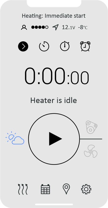
| Immediate Start Mode |
|
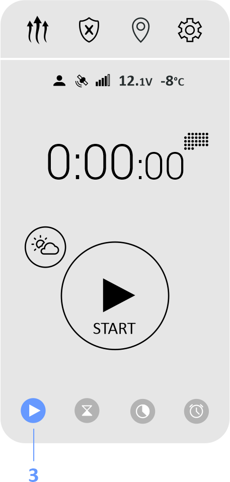
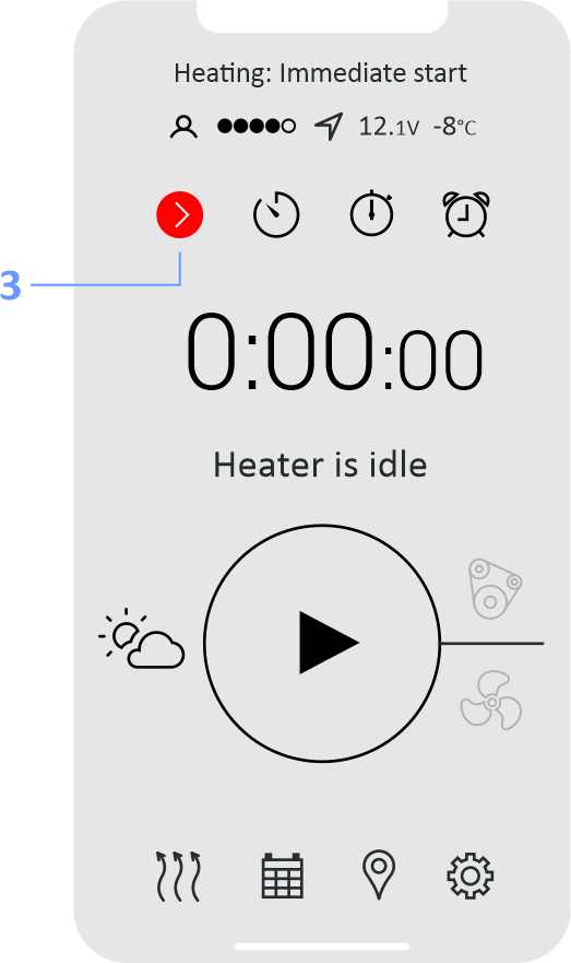
In Immediate Start mode Therminal sends start command instantly. Immediate Start mode is used as default mode at startup of Therminal. Select
"Immediate Start" in modes list, if another mode is selected at the moment.
 |
|
 |
|
| 3 — Immediate Start mode |
|
|
| Timer Mode |
|
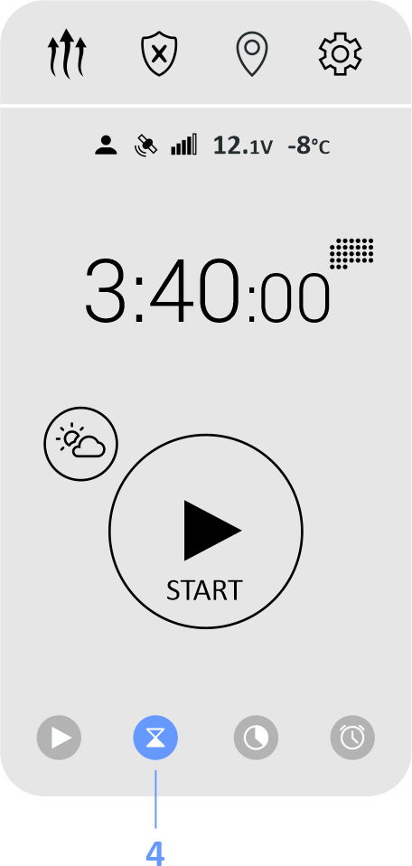
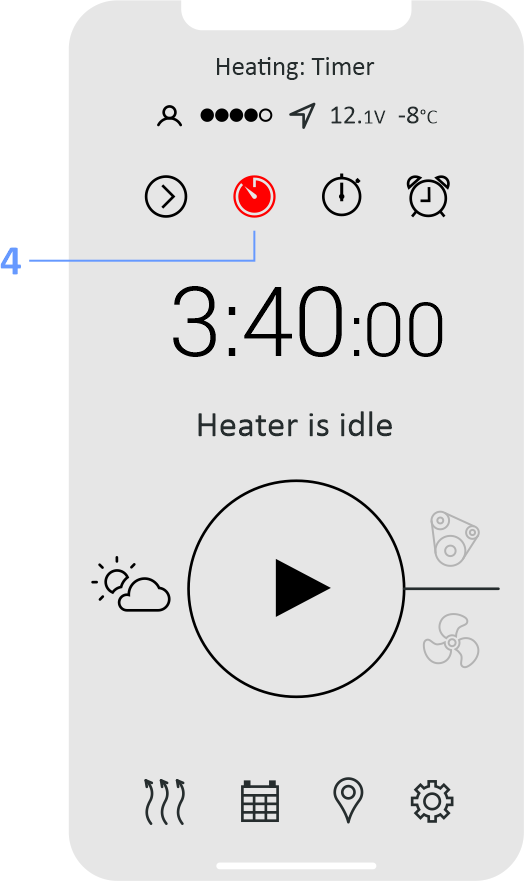
Timer Mode is intended to set delay value after which the heating will be completed. Select "Timer" in modes list. Tap on current value of the timer to adjust
another value. Push Start/Stop button to start timer.
 |
|
 |
|
| 4 — Timer mode |
Note: Heater start command will be sent at the moment when calculated start time achieved. Network services availabilities are required.
|
|
| Limit Operation Time Mode |
|
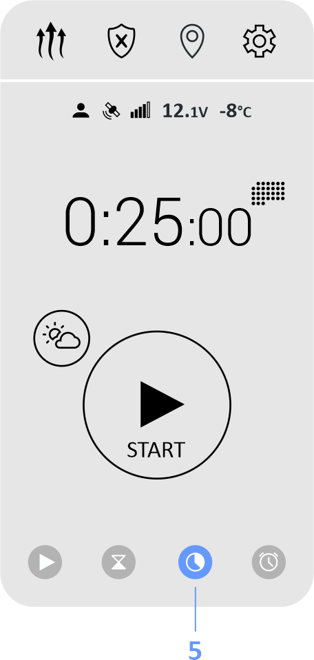
This mode is the same as Immediate Start mode, but operation time of the heater can be limited for current heating cycle without changing of "Heater operation time"
setting. Select "Limit operation time" in modes list. Tap on current value of operation time to adjust another value. Push Start/Stop on-screen button to start the heater.
 |
|
 |
|
| 5 — Limit Operation Time mode |
Note: Cycle duration can be selected only less than "Heater operation time" value. If Weather button is active, operation time may be additionally limited
by weather conditions.
|
|
|
| Pickup Time |
|
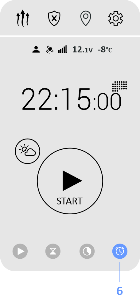
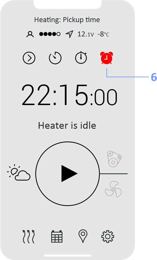
In the "Pickup Time" mode user selects time during a day, at which the heating will be finished. Select "Pickup Time" in modes list. Tap on the current value of pickup
time to adjust another value. Push Start/Stop button to activate the mode.
 |
|
 |
|
| 6 — Pickup Time mode |
Note: Therminal calculates startup time at 2 hours before the pickup time. Heater start command will be sent at the moment when calculated start time
achieved. Network services availabilities are required.
|
|
| Operation Time According to Weather Conditions |
|
Heater operation time can be derived automatically according to weather conditions. Application uses vehicle location (if available) or smartphone location
in calculations. The function works with both fuel and electric heaters. Push screen button with weather logo to activate the function. The function needs internet access via Wi-Fi
or mobile data.
Note: Being activated the function is applied to all of heater start modes, including schedules.
|
|
|
| Ventilation and Engine Control Buttons |
|
If equipment configuration allows control ventilation separately from heating and/or start the engine during heating, ventilation and/or engine control
buttons will be available. Ventilation (for interior warm up) and engine start turns on according to the algorithm and current settings of Therminal. Select required control
mode by pressing corresponding screen button before heater startup.
 |
|
 |
|
| 7 — Ventilation and Engine Control Buttons |
Note: Being activated the function is applied to all of heater start modes, including schedules.
|
|
|
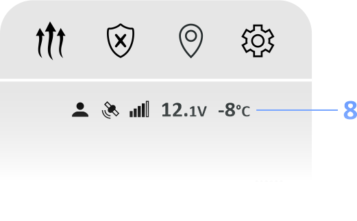
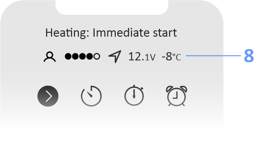
| Status Bar |
|
The app displays in status bar the values of interior temperature and battery voltage, and also several icons:
Driver icon. Highlighted icon means, that user is the active one or the driver. GSM-module will send all notifications to this user.
GSM-module signal strength icon. When the signal is week (1 or 2 elements of 5), connection failures can happen.
GPS/GLONASS signal presence icon. The highlighted icon means that vehicle location data is actual.
 |
|
 |
|
| 8 — Status Bar |
|
|
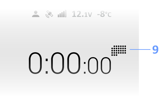
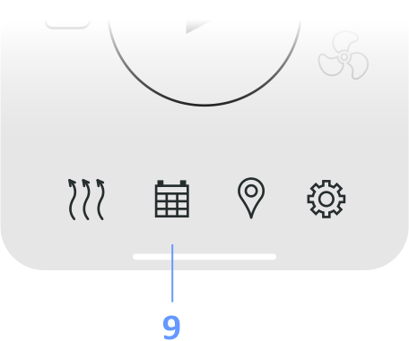
| Schedules |
|
Note: Schedules are stored in smartphone memory. Therminal calculates startup time at 2 hours before the schedule time. Heater
start command will be sent at the moment when calculated start time achieved. Network services availabilities are required.
 |
|
 |
|
| 9 — Schedules |
Note: Ready time is set in the schedules (the moment at which heating will be finished).
|
|
| One Time |
|
| One Time mode describes heating ready time for the certain date and time. The individual switch is used to enable or disable the schedule.
|
|
| Weekly |
|
| Two independent ready times for a day can be set for every day of the week. The schedule repeats every week.
|
|
| Shift Work |
|
In the Shift Work mode workdays alternate with days of rest cyclically, independently of days of week. Shift Work schedule logic:
1. It is necessary make a list of workdays and rest days in one cycle. The number of days in the list is the period of the schedule. Rest day is a day in the list with no one ready
time. Workday is a day in the list with at least one ready time.
2. Two independent ready times for a day can be set for every day of the schedule.
3. Current day (today, up to 00:00) is set by pressing on day’s index number in the list.
|
|
| Heater Control by Using Voice Call |
|
To start the heater make outgoing call on GSM-module’s number and wait for busy tone. GSM-module will confirm command reception and launching in the application
in case of control via internet, or will send SMS-confirmation, if SMS is used. Make the second call to stop the operated heater.
Note: The control by voice call is possible for registered users only.
|
|
| Heater Control by Using SMS |
|
| User can type following messages manually to control the heater: |
|
| Heater Start and Stop Commands |
|
1234 Heater On
Command starts the heater instantly for the maximum time.
1234 Heater On <time in minutes>
Command starts the heater instantly for a <time in minutes>.
Positive feedback from modem that the command received and executed:
HEATER ON: accepted, <status>
1234 Heater Off
Command stops the heater instantly.
Positive feedback from modem that the command received and executed:
HEATER OFF: accepted, <status>
|
|
| Feedback Messages |
|
When some events occur, GSM-module sends notifications (feedback messages) to the driver’s phone number:
NOTICE: Heater started — Heating started
NOTICE: Heater stopped w/timer — Heating is finished
NOTICE: Heater start error — Heater doesn’t start up
NOTICE: Heater stopped w/error — Heating failure
|
|
| Additional Commands |
|
Status request (battery voltage, temperature, balance, network signal):
1234 Get status
Location request:
1234 Get location
Balance request (get answer in operator format):
1234 Get balance
Driver identificator request for application set up:
1234 Get ipaccess
Web-console access request:
1234 Get webaccess
Connection status request:
1234 Get ipstatus
|
|
|
| Passwords |
|
In order to prevent unauthorized access to the vehicle via Therminal, users have to use passwords. Therminal provides different access levels for the
user who knows User password and for the user who knows Administrator password.
User password (marked as <password> in examples of commands below) allows
to request non-confidential information and control the heater (or other controlled device). Therminal can store 1 common user password for unregistered users to get access
via SMS and 3 personal user passwords for registered users to get access via SMS/internet.
Administrator password (<admin_password> in examples of commands
below) allows to request any information and to change Therminal settings, including User passwords.
Initially all User passwords are the same and equal to factory
value 1234. We recommend change factory password for each user in purpose of security enhancement. The user password can include digits 0-9, Latin lowercase
(a-z) and upcase (A-Z) letters and also some special symbols: !"#$%&*()-+'⁄,. User password length should be at least 4 symbols and no longer than
16 symbols.
Administrator password is a 7 digits code, which equal to last 8-1 symbols of ICCID code, printed on SIM (fig. 1). For SIM at figure 1 the administrator
password is 1234567. You can use as administrator password any part of ICCID code, which includes correct sequence of digits, i.e.: 12345678, 0121234567,
78901212345678.

The administrator password can be changed by the means of SIM replacement only.
|
|
|
| Users and Administrators |
|
Everyone who knows common user password <password> can access Therminal via SMS in order to control the heater, ventilation and the
engine.
Everyone who knows administrator password <admin_password> can access Therminal via SMS and web in order to control the heater,
ventilation and the engine and also to change settings. |
|
| Administrator |
|
User must have administrator permissions to be able to make adjustments and request confidential information.
A special command there exists to set a user as the administrator:
<admin_password> Admin
Therminal will answer with a confirmation: ADMIN: accepted, <status>
If Therminal receives SMS, beginning with admin_password, it will also store user's GSM-number as the number of administrator.
Administrator can request service information by using both user password and admin_password, but change settings — only with admin_password. |
|
|
| Active User or Driver |
|
At any moment the only one user can drive the vehicle, and similarly the only one user can have permissions to control the vehicle by using Therminal.
This user is called the Driver in this manual. The Driver receives all alarms and notifications, sent by Therminal. The user can take Driver permissions only if other user
(the current Driver) doesn't control the vehicle via Therminal or directly, inside the vehicle. In other case current Driver has to finish the control at first. No approval
from current Driver is needed to take permissions. The User only needs to know the <password> to become the Driver.
Variants for the Driver change:
1. By receiving and launching any control command (except Get and Set), beginning with <password>, Therminal will save user's GSM-number as the Driver number.
The previous Driver will get the notification DRIVER OFF: forced, <status>. New Driver can check his Driver status by the field
Status: inside the notification.
2. By the command Driver ON, which the User sends to take Driver permissions:
<password> Driver ON
Therminal confirms the command with DRIVER ON: accepted, <status>.
If other User controls the vehicle at the moment, Therminal doesn't allow the Driver change with DRIVER ON: busy, <status>
If the command is sent with <admin_password>, the module will deny the operation with DRIVER ON: denied, <status>
3. By the command of temporary refusal from Driver permissions Driver OFF
<password> Driver OFF
The Driver permissions temporary will be given from the User to the Web-user (means that all notifications will be redirected to the server). Refusal is active up to the module restart,
whereupon the User becomes the Driver again. Accordingly the command doesn't change the Driver number stored in Therminal memory.
The command is confirmed with DRIVER OFF: accepted, <status>. If the command was sent with <admin_password>, the module
ill deny the operation with DRIVER OFF: denied, <status>.
If the command is sent by the User, who is not the Driver, he only receives a confirmation DRIVER OFF: accepted, <status>, but
the Driver remains the same. The refusal is possible only if the Driver doesn't control the vehicle via Therminal. Otherwise he receives
DRIVER OFF: busy, <status>.
The command is primarily used to disable the notification from the module.
4. By the command Set Driver, which is used by the Administrator to transfer the Driver permissions to the particular User.
<admin_password> Set Driver=<number>
Where <number> can take values USER1, USER2, USER3, SELF, EMPTY, BACK, or can be a GSM-number.
The command is confirmed by SET DRIVER: accepted, <status>. It transfers the permissions forcibly and independently to the fact,
whether the Driver controls the vehicle via Therminal or not. The SMS-user, which receives Driver permissions, has to know the <password> to be able control Therminal.
Otherwise he can only receive notifications from Therminal.
If permissions transfer was successful, Therminal sends to the previous Driver the notification
DRIVER OFF: forced, <status>, to the current Driver —
DRIVER ON: forced, <status>.
Note: The possibility to receive the SMS-notifications about Driver change can be adjusted in the table settings individually for every registered user
and separately for all unregistered users.
|
|
|
| Multi-User Mode |
|
The device can store up to 3 phone numbers of regular users (register them). The registration procedure is necessary in some cases:
1. User wants to control Therminal via voce call
2. User needs personal permissions to request vehicle location
3. User wants to control Therminal from applications via Internet
Registration of users is managed by the Administrator. The first user can be registered automatically during Quickstart procedure launching. Other users need to be
registered by the administrator, via SMS command or from web-panel.
|
|
|
| Users Registration |
|
The commands intended for user list managing:
1 The administrator's request which adds user's GSM-number to the list of registered users:
<admin_password> Set users=<position>.<phone_number>[,<position><phone_number>[,<position>.<phone_number>,]]
The command creates a new user with the name User<position> for access to Therminal. Parameter <position> point to the position in the registered users list, 1-3.
The position affects on user's permissions to request car location (than farther from 1 — than lower priority). E.g.
1234567 Set users=2.+12344444444
1234567 Set users=2.+12344444444,3.+12345555555
Therminal confirms the command with SET USERS: accepted, <status>.
If at least one of the numbers in the parameters list is registered yet in another position, Therminal will refuse the registration with
SET USERS: denied, <status>.
It is necessary to delete this number from registered users list at first by the
command <admin_password> Set users=<position>.EMPTY or save to this position the number of another user.
For every registered user Therminal creates a personal password, initially the same as the common user password <password> at the moment of user registration.
It can be changed later by the administrator (usually with the purpose to achieve more confidentiality inside the group of IP-users). If the personal password has not been
individually changed, the change of the common password will also change the personal password.
The registered users list is stored in SIM memory. It is necessary
to reregister the users after SIM replacement.
2 <admin_password> Set users=Default — resets the
registered users list.
|
|
|
| Answers from Therminal |
|
Answer — is a reaction of Therminal to the user's command. It will be sent only in case of valid <password> or <admin_password> at the beginning
of the command is present (for all the users including the registered ones). Otherwise the command will be ignored for security reasons.
If the password is valid, but:
1. The command is not supported (did not recognized by Therminal), it will be answered by notification Command error, <status>
2. There is an error in the command format (invalid separators, invalid directives, invalid parameters). In this case Therminal answers with error message, including the initial command
and error directive, e.g:
SET TIME: error, <status>
If Therminal receives a valid message, it answers with confirmation message, including the initial command completely or partially, e.g:
HEATER ON: accepted, <status>
If Therminal at the moment is used by another user, it answers with busy notification:
HEATER ON: busy, <status>
If the user has no permissions for command launching (e.g. administrator password is required instead of user password), Therminal answers with restriction message, including the initial
command and denied directive:
SET PASSWORDS: denied, <status>
|
|
|
| Therminal Registration. QuickStart Procedure |
|
The Android and iOS apps control the Therminal via Internet. High secure internet connection server is used for data transfer. In order to the server be able send
and receive data between the app and Therminal, the special registration procedure should be performed on the server.
The device uses GPRS technology in a 2G GSM network. It is important to make sure the GPRS is available on GSM-operator's side before the registration.
Therminal stores GPRS settings (APN, login and password) for Russian and Scandinavian GSM operators. GPRS settings are selected automatically for these operators. User also can adjust
the GPRS settings manually by the command Set GPRS, in case if settings for the operator don't present in the device.
The command <admin_password> Register starts server registration process for the Therminal. The registration may be performed independently of
INTERNET setting value. User can check the registration status by the command <admin_password> Get IPSTATUS or
<password> Get IPACCESS (for a registered user only).
There exists a special procedure Quickstart, which includes simplified the first (main) user registration, server registration and also requests the access to administrative
web-console. The procedure may be started in two ways:
1 Press and hold the LED button for at least 10, but not more than 15 seconds, then release the button. The LED will flash with 10 flashes
in series. During 3 minutes make a voicecall on Therminal's number. The device will reject the call with busy tone, store the caller's number as USER1, ADMIN и DRIVER, allow server
access (Set INTERNET=ON) and start server registration procedure (Register). At the end of registration the LED stops flashing, Therminal sends SMS with registration
results. Then the device will make web-console access request (Get WEBACCESS) and then will send SMS with request results.
The procedure can be started in such a
manner only once, and only until the device doesn't store driver's number. The repeated start will be possible only after full reset of Therminal to the factory settings
(Set DEVICE=FACTORY) is done.
2 Send on Therminal's number SMS <password> Quickstart. The device will store the sender's number as
USER1, ADMIN и DRIVER, allow server access (Set INTERNET=ON) and start server registration procedure (Register). At the end of registration the LED stops flashing,
Therminal sends SMS with registration results. Then the device will make web-console access request (Get WEBACCESS) and then will send SMS with request results.
The procedure can be started with user password (factory value — 1234) only once, and only until the device doesn't store driver's number. The repeated start will be possible only
after full reset of Therminal to the factory settings (Set DEVICE=FACTORY) is done. Anytime Quickstart can be repeatedly started with the administrator
password.
If during Quickstart execution the automatic registration was failed, the administrator can make changes in server access settings and repeat the registration manually by
the command Register.
|
|
|
| Control Commands |
|
User controls the heating, ventilation and engine remote start by typing SMS manually or via application interface of its smartphone. In this case commands
will be generated automatically.
Commands should be typed in Latin letters only, in lower or upper case (except passwords — case sensitive).
Command format in common:
[<password> space] <command>[space or =][<command parameter>][space <command parameter>][space <command parameter>]
Device control commands
Therminal is able to control the devices:
Fuel fired heater, engine remote start module, climate control module, AC electrical heater for engine and interior compartment. Commands intended for the direct control:
<password> Heater on — Turn on the fuel fired heater
<password> Heater off — Turn off the fuel fired heater
<password> Eheater on — Turn on the electrical heater
<password> Eheater off — Turn off the electrical heater
<password> Climate on — Turn on the climate control module
<password> Climate off — Turn off the climate control module
<password> Engine on — Start the engine
<password> Engine off — Stop the engine
Parameters
<numerical value 1..255> - operational time of the process in minutes, e.g:
<password> Heater on 30 turns the fuel heater on and limit its operational time by 30 minutes.
It can be set in parameters for the fuel and electrical heater how to use ventilation and engine start during the heating process:
<password> Heater on +fan will apply table settings (4.4) to activate interior warm up.
<password> Heater on +engine will apply table settings (4.6,
4.8) to activate engine start.
<password> Heater on 15 +engine +fan will turn on the fuel heater for 15 minutes applying settings of ventilation and engine start
activation.
Administrative commands
1. <admin_password> USSD<command>
Transfer USSD code to the module in order to launch it in GSM serving network. Command is intended to control the provider's services. Reception of the command is not confirmed by
the GSM-module.
Network response for USSD code will be sent to the user as a message with USSD: prefix. Dialog USSDs are not supported.
If the user has no
permissions to apply the command, the module will answer with USSD: denied, <status>
2. <admin_password> Restart performs the reload of Therminal. The reload may be needed after settings change, e.g. command is not confirmed.
It can be used with user password also, if sent from the administrator's number.
3. <admin_password> Powerdown — command forcedly goes Therminal to the Powerdown mode. In this mode GSM and GPS modules are switched off to
minimize power consumption. The mode allows to leave the vehicle (with Therminal connected and powered) unused for a long period of time without need to disconnect Therminal from power.
Supply current in Powerdown mode is less than 1mA (for 12 Volt power). Possible inactivity time in the mode is defined by self-discharge characteristics of vehicle's battery in fact
(about a half of the year).
In order to go Therminal back to the Normal mode, user can press the LED button or disconnect and then repeatedly connect the module (suitable for Plug-n-Play connection to the
OBD-II service socket). The command is confirmed by Powerdown: accepted, <status>; the Driver receives the notification
NOTICE: Powerdown mode, <status>
If power save modes are adjusted by the settings, Therminal automatically goes to Powerdown mode, if the vehicle stays unused (no engine starts) for longer than 60 days period.
4. <admin_password> Standby — command forcedly goes Therminal to the Standby mode. In this mode GSM and GPS modules are switched off to minimize
power consumption. The mode allows to leave the vehicle (with Therminal connected and powered) unused for a long period of time without need to disconnect Therminal from power.
Supply current in Standby mode is less than 5.5 mA (for 12 Volt power). Possible inactivity time in the mode is about 2 months.
In order to go Therminal back to the Normal mode, user can press the LED button. Also Therminal automatically goes to the Normal mode when the engine starts (battery voltage achieves
13.5 Volts) or alarm is triggered.
Command's action is equal to automatic transition to power save mode after 14 days inactivity (with the setting
1.9.4 applied).
The command is confirmed by STANDBY: accepted, <status>; the Driver receives the notification
NOTICE: Standby mode, <status>.
5. <password> Normal — command forcedly goes Therminal to the Normal mode from one of power save modes, when it possible (depends from
1.9 settings and power save mode stage). The command is confirmed by
NORMAL: accepted, <status>; the Driver receives the notification
NOTICE: Normal mode, <status>
When the command is launched in Normal mode, it resets inactivity timers (imitates driver
activity).
|
|
|
| Get Command for Parameters Requesting |
|
The command is intended to request settings, parameters, access codes, etc. from Therminal. The common format is:
<password> Get <parameter>
Common format for answers:
<parameter1>:<values>, parameter2>:<values>,…,<parameterN>:<values>
|
|
Parameter Name
|
Parameter Description
|
Parameter Requesting Details
and Answers from Therminal
|
| balance |
Balance response |
1234 Get balance
Response:
USSD: <operator's response
text> |
| errors |
Last fixed errors |
1234 Get gpsdata
Response:
CMEC:<CME error code>,
CMSC:<CMS error code>,
TCPEC:<TCP error code>,
ALEC:<AES Link error code>,
RTEC:<runtime error code, BCD format>,
EEC:<EEPROM error code, BCD format>,
HREC:<heating error code>
|
| gpsdata |
Last actual (most recent) data of GPS receiver |
1234 Get gpsdata
Response:
LAT:<latitude coordinate of GPS position>,
LONG:<longitude coordinate of GPS position>,
SPEED:<speed in km/h>,
COURSE:<course in degrees>,
TFIX:<coordinates fix time, local>,
DFIX:<coordinates fix date, local>,
[GTFIX:<coordinates fix time, by Greenwich>,
GDFIX:<coordinates fix date, by Greenwich>]
CELL:<TA,MNC,MCC,LAC,CID> — CELL monitoring parameters for GSM network.
The user should have permissions for location requesting, otherwise the response will be: GPSDATA:n/a, CELL:n/a
|
| hardware |
Hardware table settings |
<admin_password> Get hardware
Response:
HARDWARE:1.F11111111111111,2.11111111111111
The request can be used with user password, but only if sent from the administrator's number. Letters A,B,C,D,E,F mean values 10,11,12,13,14,15 respectively.
|
| info |
Device identification data |
1324 Get info
Response:
DEVICE: <device name>,
VERSION:<device firmware version>,
HWID:<hardware identificator>,
IMEI:<GSM-modem identificator>,
PROVIDER:<MCC/MNC of GSM provider>,
OPERATOR:<MCC/MNC of current GSM operator>,
TIME:<device local time>,
DATE:<device local date>
|
| ipaccess |
Data for access from applications via internet |
1234 Get ipaccess
Response:
USERID: <driver identificator>, PASSWORD:<user password>
IPACCESS:n/a, if GSM-module is not registered on server (see Quickstart,
Register commands)
GET IPACCESS: denied, if user's GSM-number is not registered in the device (see Set users command)
|
| ipstatus |
Server connection status and the current GPRS and server settings |
1234 Get ipstatus
Response:
GROUP:<users group identificator¹>,
IPSTATUS:<connection status: online/offline>,
SERVER:<servicing internet connection server>,
PORT:<port number>,
PERIOD:<server connection interval²>,
GPRS:<attached/detached>,
APN:<GPRS access point name>,
APLOG:<GPRS access point login>,
APPAS:<GPRS access point password>
¹GROUP:n/a, if GSM-module registration is not performed (see Quickstart,
Register commands)
²GROUP:OFF, if access to the server is switched off by the command Set internet=off
|
| location |
Vehicle's location by GPS/GSM signals as a http link to map |
1234 Get location
Response:
LOCATION at <time>, <date>: <URL-link to map>
The user should have permissions for location requesting;
If (GMT) follows <time>, <date>, the timestamp is fixed by Greenwich time.
|
| passwords |
Users' passwords requesting (common and personal) |
<admin_password> Get passwords
Answer (factory settings):
COMMON:1234, PERSONAL 1:1234, PERSONAL 2:1234, PERSONAL 3:1234
|
| statistics |
GSM-modem operation statistics |
1234 Get statistics
Response:
SYNCPOINT:<the time of clock synchronization>,
LDA:<last driver activity> (activity by network is not took into account),
REBNUM:<the modem restarts number>,
LRREAS:<the modem last restart reason>,
LSREAS:<the modem last shutdown reason>,
ERRATE:<the number of unsuccessful/successful connections with the server>
STO:<server timeout value (characterizes the connection quality), seconds>
SMS:<the number of authorized incoming SMS / all incoming SMS/outgoing SMS>
CALL:<the number of authorized incoming calls / unauthorized incoming calls>
|
| status |
Requesting of vehicle's components statuses |
1234 Get status
Answer example:
STATUS:e.h.c.o.U,VOLT:12.3, TEMP:+12, BALANCE:74.2, LONG:n/a, LAT:n/a, CELL:1.250.99.A482.8B16, NET:2/5R
STATUS field description:
a — alarm mode is off (disarmed),
A — alarm mode is on (armed);
e — engine is stopped,
E — engine is running;
h — fuel heater is off,
H — fuel heater is on;
с — ventilation (climate control module) is off,
С — ventilation (climate control module) is on;
o — electrical heater is off,
O — electrical heater is on (virtual status);
u — user is not the Driver,
U — user is the Driver
If some device has no actual status (status is unknown), its status will be missed in the list.
VOLT:<battery voltage, 0…30.0 Volts>,
TEMP:<thermo sensor value, -50…+90°C>,
BALANCE:<digital value extracted from response for the balance request>,
LAT:<latitude coordinate of GSP position (last known) or n/a>
LONG:<longitude coordinate of GPS position, (last known) or n/a>,
CELL:<TA,MNC,MCC,LAC,CID или n/a - CELL monitoring parameters for GSM network>,
NET:<GSM signal strength level 1..5/5><R-roaming mode>
|
| table |
Software table settings |
<admin password> Get table
Response:
TABLE: 1.353B11111111111, 2.23411111111111A,… 9.151111111111111
The request can be used with user password, but only if sent from the administrator's number
|
| users |
Registered users numbers list, administrator and driver numbers |
<admin password> Get users
Response:
ADMIN:<administrator's GSM-number>,
DRIVER:<driver's GSM-number>,
USER1:<GSM-number of user 1>,
USER2:<GSM-number of user 2>,
USER3:<GSM-number of user 3>
The request can be used with user password, but only if sent from the administrator's number
|
| webaccess |
Access to the administrative web-console |
1234 Get webaccess
Response:
WEBACCESS:<web-console access status: on/off*>, URL:<http(s) link to the web-console sign in page>,
LOGIN:<user's login>, PASSWD:<user's password>
*In order to control the GSM-module via web-console it is necessary to allow web access by the command Set webaccess=on
(factory setting is on).
In case of unsuccessful request to the server for web-console access (no connection, GPRS is not adjusted, server registration is not performed) the modem will response with the answer:
WEBACCESS:n/a, <ipstatus>
|
|
| Set Command for Parameters Change |
|
The Set command is intended for GSM-module parameters change. Common command format:
<admin password> Set <parameter>=value1,...valueN
Only the administrator may execute the command and get answer. The detailed description of command parameters is presented in table 2.
|
|
Parameter Name
|
Parameter Description
|
Parameter Requesting Details
and Answers from Therminal
|
| passwords |
Users passwords control |
<admin password> Set passwords=0.<common password>[,1.<USER1 password>][,2.<USER2 password>][,3.<USER3 password>]
<admin password> Set passwords=default — resets common password to default value 1234, deletes users' personal passwords
The module answers with command accept confirmation + the answer on Get passwords request.
Example:
<admin password> Set Passwords=3.myford,0.3456,2.,1.
change personal password for the USER3 to myford,
common password — to 3456,
delete personal password for the USER2 (reset to common value),
delete personal password for the USER1 (reset to common value)
|
| device |
Full device reset to the factory settings* |
<admin password> Set device=factory
*Do not erase users' GSM numbers (stored in the SIM)
Command is not confirmable
|
| users |
Users list control — registration and deletion |
<admin password> Set users=1.[,2.][,3.]
<value>=empty — position reset
<value>=<empty> — position reset
<value>=self — registers the own number (administrator's number)
<admin password> Set users=default — resets users list
Example:
<admin password> Set users=1.+123456789,3.empty,2.
The module answers with command accept confirmation + the answer on Get users request.
|
| time |
Local time adjustment (also sets automatically from incoming SMS) |
<admin password> Set time=<hh:mm>
sets local time in the device.
The module answers with command accept confirmation + the answer on Get info request.
|
| date |
Local date adjustment (also sets automatically from incoming SMS) |
<admin password> Set date=<dd-mm-yyyy>
sets local time in the device
The module answers with command accept confirmation + the answer on Get info request
|
| GPRS |
GPRS-connection parameters for GSM-module's SIM provider (GPRS profile) |
<admin password> Set GPRS=<profile>[,[<access point>],[<login>],[<password>]]
<profile>=custom — user defined settings. The missed parameter is not changed, * deletes (sets to empty value) the parameter, i.e:
<admin password> Set gprs=custom — apply custom user settings
<admin password> Set gprs=custom,,guest,* — modify and apply custom settings: leave APN, change login to guest, delete password
<admin password> Set gprs=custom,internet,, — Telia Suomi APN settings
<profile>=auto — select GPRS settings automatically (factory settings)
<profile>=default (or 0) — select default GPRS profile (mostly often used settings: internet,,)
The module answers with command accept confirmation + the answer on Get ipstatus.
|
| internet |
Internet access control |
<admin password> Set internet=<on/off>
Factory value — off
The module answers with command accept confirmation + the answer on Get ipstatus
The request can be used with user password (factory value - 1234), but only if sent from the administrator's number.
|
| webaccess |
Web-server access control |
<admin password> Set webaccess=<on/off>
Factory value — on
If access is switched off, the setup web-console and schedules of startups in the apps will be unavailable.
|
| balance |
Adjusting of USSD-code for GSM account's balance requesting
May be usable for prepaid accounts only
Contact GSM provider for details.
|
<admin password> Set balance=<code>
<admin password> Set balance=default — reset code to default value (#100#)
<admin password> Set balance=auto — select code automatically by provider's profile (factory settings)
|
| driver |
Set the Driver |
<admin password> Set driver=<value>
where <value> is:
USER1, USER2, USER3 — assign one of the registered users,
SELF — assign yourself,
EMPTY — temporary assign the web-console user (administrator),
BACK — restore the Driver after temporary assigning the administrator as the Driver, or phone number in format, permitted by table setting 9.7.
The module answers with command accept confirmation + the answer on Get users
|
| table |
Software table settings adjustment (see table 5 for codes) |
<admin password> Set table=<code 1>[,<code 2>]…[,<code N>]
Set table=default — reset software table setting to the default values and restart the module
Some settings take effect only after restart will be performed (see Restart command)
Example:
<admin password> Set table=111,121,7F2
|
| hardware |
Hardware table settings adjustment (see table 6 for codes) |
<admin password> Set hardware=<code 1>[,<code 2>]…[,<code N>]
<admin password> Set hardware=default — reset hardware table setting to the default values and restart the module
Any settings take effect only after restart will be performed (see Restart command)
|
|
| Notifications |
|
When the status of the controlled by Therminal device changes, it sends a notification message for the Driver. The type of notification — SMS or data packet — is
defined by the type of last command, received from the Driver.
Notification format:
NOTICE: <notification text>, <status>
Possible notifications:
NOTICE: Heater started w/command, <status>
NOTICE: Heater started w/voicecall, <status>
NOTICE: Heater started w/input, <status>
NOTICE: Heater started w/button, <status>
NOTICE: Heater stopped w/…, <status>
NOTICE: Heater start error (), <status>
NOTICE: Heater stopped w/error (), <status>
NOTICE: Engine started w/…, <status>
NOTICE: Engine start error, <status>
NOTICE: Engine stopped, <status>
NOTICE: Climate started w/…, <status>
NOTICE: Climate stopped w/, <status>
NOTICE: Normal mode, <status>
NOTICE: Standby mode, <status>
NOTICE: Powerdown mode, <status>
NOTICE: Shutdown mode. Battery discharged, <status>
NOTICE: Powersave mode/internet off, <status>
NOTICE: Powersave mode/sleep stage 5 h 45 min, <status>
NOTICE: Powersave mode/active stage 15 min, <status>
NOTICE: Powersave mode/deep sleep stage, <status>
NOTICE: Registration successful, <status>
NOTICE: Registration failed, <status>
|
|
|
| Multi-Control Messages |
|
Up to 7 commands can be transferred inside one message. To separate commands the semicolon (';' without spaces before or after the separator) is used, i.e:
<admin_password> Set table=123;Restart
The commands Register, Quickstart, Get Webaccess, Get Balance, USSD (all commands, which need dialog data transfer with the network or the server),
Set Driver, Restart, Set Device=Factory have to be placed at the end of the list, because all commands placed after these will be ignored.
The module can answer for multi-control message with no more than 7 messages. Wherefore if there is a command inside multi-control message which leads to the Driver change
(+2 messages to the answer), the commands number should be accordingly decreased.
The answers for commands will be sent in the same sequence as commands are listed in multi-command.
|
|
|
| Button and Indication |
|
The GSM-module is equipped with outer button with integrated LED. During 2 minutes after powering up or restarting the LED indicates device status by flashes
in series. The indication also stops after starting the engine in order to don't divert the driver.
The button's main function is defined by table setting 2.7 (fuel heater one touch control by default). In order to activate the main function briefly press and release the button.
If the button is pressed at the moment when periodic indication mode (status indication, Quickstart indication, signal strength indication) is active, the first pressing will cancel
periodic indication mode. And only next pressings will control the button's main function. The button is blocked in the Armed mode and is not functional.
|
|
Number of flashes in series
|
Status description
|
The possible reasons and actions required
|
| 1 |
Armed mode |
The device is armed. It is necessary to disarm the device by one of allowed by configuration methods before going to the trip in order to
prevent of alarm triggering.
|
| 2 |
GSM inactive |
The device is not available for control via cellular network, GSM-modem is switched off. If the device went to this mode after powering up,
it can be caused by one of problems: PIN-code accepting is on, SIM is out of order, the registration in the network is prohibited by the operator (i.e. SIM-card is out of
service, SIM is blocked). The problem should be solved.
|
| 3 |
Waiting for GSM ready |
The device is starting and temporary unavailable for control via cellular network. No action required from the user.
|
| 4 |
Waiting for GSM registration |
The device is temporary unavailable for control via cellular network. Possible reasons: no available network (no signal, roaming mode
is prohibited), registration is blocked by operator (i.e. because of long inactivity time). The network signal strength can be checked by applying special LED indication
mode from the button.
|
| 5 |
Ready for the command accepting |
The device is ready for control via cellular network. If the device doesn't answer for SMS, and the app informs "Vehicle is offline",
check at first GSM account condition by using the provider's service.
|
| 6 |
Ready for the command accepting, roaming mode |
The device is ready for control via cellular network with some limitations (see table setting 1.3)
|
| 10 |
QuickStart mode |
QuickStart mode is active. The device is waiting for incoming call, if the mode was activated from the button.
|
|
If the button's main function is emergency button, all registered users (except of the Driver) will receive emergency message as SMS
and a data packet (via server) when the button is pressed. The message format is:
SOS! ATTENTION! THE DRIVER <GSM subscriber's number> NEEDS HELP! VEHICLE LOCATION at hh.mm dd.mm.yyyy: <link on a map>
In order to execute additional button's functions press and hold the button for a period of time, specified by table 4. The LED will go on and start flashing with 1 second period.
Release the button in several seconds after pressing in order to execute specific function:
|
|
Hold time
|
Function
|
| 1-5 seconds |
Exits from Standby and Powersave modes
|
| 5-10 seconds |
Switches on status indication mode. Shortly press the button to exit the mode.
|
| 10-15 seconds |
Activates Quickstart. The device will wait for incoming call during 3 minutes after the activation.
|
| 15-20 seconds |
Switches on the GSM signal strength indication mode. Very short flashes in series are used to indicate signal strength. One flash
corresponds to the lowest level of signal, five flashes correspond to the highest level of signal. There are no flashes If the signal is absent at all. Information
is updated every 10 seconds. The function can be used in order to find place for the antenna/module inside the vehicle during installation procedure. Shortly press
the button to exit the mode.
|
| 20-25 seconds |
Restarts the device.
|
| 25-30 seconds |
Partial device reset to the factory settings. Registered users' numbers (placed on SIM), the Driver's number, the administrator's
number will not be cleared.
|
|
| Software Table Settings |
|
All other settings are not presented in the chapter 11 (except hardware settings) can be found in the table 5. In order to apply the setting
send command Set table with setting code as a parameter.
For example: <admin password> Set table=111,121,7F2
|
|
| 1 GSM user settings |
11
Reaction for incoming call from registered number |
111 Hang up with busy tone
112 Hang up with busy tone, send status message
113 Hang up with busy tone, send confirmation for the command of switching on, switch on the controlling device (see 1.2 setting)
114 *Hang up with busy tone, send confirmation for the command of device status changing, put the controlling device (see 1.2 setting) in the opposite state
117 Hang up with busy tone, initiate data request from the server
|
12
Incoming call controlling device |
121 Fuel fired heater
122 Engine remote starter
123 Climate module (in ventilation mode)
12A Electrical heater of engine (interior)
|
13
Roaming mode behavior |
131 Like at home network
132 Switch off GPRS for any type of roaming
133 Switch off GPRS, don't send SMS for any type of roaming
134 Switch off GPRS, don't send SMS for any type of roaming, except of answers and alarm notifications
135 Switch off GPRS for international roaming
136 Switch off GPRS, don't send SMS for international roaming
137 *Switch off GPRS, don't send SMS for international roaming, except of answers and alarm notifications
|
14
Users group having permissions to request of vehicle location |
141 All the users knowing the password
142 All registered users 1,2,3
143 Registered users 1 and 2
144 *Registered user 1
145 Only the administrator (also with user password)
|
18
Balance value position inside the answer on balance USSD-request |
181 *First digital value
182 Second digital value
…
18F Fifteen digital value
|
19
Power save modes
It is recommended to send the command Normal before changing
this setting: it prevents unpredictable switching to the active phase of power save mode |
191 Mode 1: Going to Shutdown mode — (disconnecting GSM-modem and GPS receiver) when battery voltage lowers to 11 Volts (instead
of threshold set by 99 setting), with notifying the driver that battery is discharged. Returning to Normal mode — when battery voltage becomes higher than 13.5 instead of
threshold set by 98 setting). If the vehicle is not used during 60 days, the device will go to Powerdown mode.
192 Mode 2: Mode 1 + GPRS (and data transfer via server) will be disconnected in 8 days of driver inactivity (no ordinary vehicle usage). SMS and calls remain available.
193 Mode 3: Mode 1 + in 8 days of driver inactivity GSM-modem will be powered by schedule: 4 times a day for 15 minutes in order to receive a power control command (Normal,
Powerdown, Standby).
194 *Mode 4: Mode 3 + in 14 days of driver inactivity GSM-modem will be disconnected at all until the alarm system triggers or driver activity will be detected.
19F Power save modes off, Normal mode of operation (GSM-modem is always online)
|
2
Control settings |
27
Button main function |
271 *Fuel fired heater control
272 Ventilation control
275 Electrical heater control
279 Emergency button
27F Not adjusted
|
3
Security settings |
3A Max value of alarm triggering counter for notifying via SMS (resets by engine starting) |
3A1 1 alarm
3A2 2 alarms
3A3 3 alarms
3A4 4 alarms
3A5 *5 alarms
3A6 6 alarms
3A7 7 alarms
3A8 8 alarms
3A9 9 alarms
3AA 10 alarms
3AB 11 alarms
3AC 12 alarms
3AD 13 alarms
3AE 14 alarms
3AF 15 alarms
|
4
Heating settings (fuel and electrical heaters) |
41
Limitation of one cycle time for fuel fired heater (if not specified inside a command) when it starts remotely. Resets by engine starting |
411 Not applied
412 10 minutes
413 15 minutes
414 20 minutes
415 25 minutes
416 30 minutes
417 35 minutes
418 40 minutes
419 45 minutes
41A 50 minutes
41B 55 minutes
41C *60 minutes
41D 65 minutes
41E 70 minutes
41F 75 minutes
|
42
Limitation of total operation time (calculates as a sum of operation times in several cycles) for fuel fired heater. Resets by engine starting |
421 Not applied
422 20 minutes
423 40 minutes
424 60 minutes
425 80 minutes
426 100 minutes
427 *120 minutes
428 140 minutes
429 160 minutes
42A 180 minutes
42B 200 minutes
42C 220 minutes
42D 240 minutes
|
43
Battery voltage threshold for heating cut-off.
For 24-voltage power the values should be
multiplied by 2 |
431 11.2 V
432 11.3 V
433 11.4 V
434 11.5 V
435 11.6 V
436 *11.7 V
437 11.8 V
438 11.9 V
439 12.0 V
43A 12.1 V
43B 12.2 V
43C 12.3 V
43D 12.4 V
43F Not applied
|
44
Conditions for interior heating enabling, by time of fuel heater operation (applied when +FAN parameter is presented in the command HEATER ON,
when the heater was started from the button, by external input or by voicecall) |
441 *Not applied (for aftermarket heater)/factory algorithm (factory installed heater)
442 Switch on together with the heater (in fact - in 3 minutes after the heater startup)
443 Switch on in 5 minutes after the heater startup
444 Switch on in 7 minutes after the heater startup
445 Switch on in 10 minutes after the heater startup
446 Switch on in 15 minutes after the heater startup
447 Switch on in 20 minutes after the heater startup
448 Switch on in 25 minutes after the heater startup
449 Switch on in 30 minutes after the heater startup
|
45
Conditions for interior heating activation, by time of electrical heater operation (applied when +FAN parameter is presented in the
command EHEATER ON, when the heater was started from the button, by external input or by voicecall).
If no operation time parameter is presented in the command Heater On, then maximum heating time for electrical heater — 180 minutes — is used for interior
heating start point calculation |
451 Not applied
452 20 minutes before heating completion
453 30 minutes before heating completion
454 40 minutes before heating completion
455 50 minutes before heating completion
456 *60 minutes before heating completion
457 70 minutes before heating completion
458 80 minutes before heating completion
459 90 minutes before heating completion
45A 100 minutes before heating completion
45B 110 minutes before heating completion
45C 120 minutes before heating completion
45D 130 minutes before heating completion
45E 140 minutes before heating completion
45F 150 minutes before heating completion
|
46
Battery voltage threshold for engine start activation during the fuel heater operation (applied when +ENGINE parameter is presented in
the command HEATER ON, when the heater was started from the button, by external input or by voicecall).
For 24-voltage power the values should be
multiplied by 2 |
461 11.3 V
462 11.4 V
463 11.5 V
464 11.6 V
465 11.7 V
466 11.8 V
467 11.9 V
468 12.0 V
469 12.1 V
46A 12.2 V
46B 12.3 V
46C 12.4 V
46D 12.5 V
46F *Not applied
|
48
Conditions for engine start activation, by time of fuel heater operation (applied when +ENGINE parameter is presented in the command HEATER ON,
when the heater was started by external input or by voicecall).
Not applied for startup from the button |
481 *Not applied
482 3 minutes after the heater startup
483 5 minutes after the heater startup
484 7 minutes after the heater startup
485 10 minutes after the heater startup
486 15 minutes after the heater startup
487 20 minutes after the heater startup
488 25 minutes after the heater startup
489 30 minutes after the heater startup
48A 35 minutes after the heater startup
48B 40 minutes after the heater startup
48C 45 minutes after the heater startup
48D 50 minutes after the heater startup
48E 55 minutes after the heater startup
48F For a time, selected in 53, before heating completion
|
49
Conditions for engine start activation, by time of electrical heater operation (applied when +ENGINE parameter is presented in the command EHEATER ON,
when the heater was started by external input or by voicecall).
Not applied for startup from the button |
491 *Not applied
492 20 minutes after the heater startup
493 30 minutes after the heater startup
494 40 minutes after the heater startup
495 50 minutes after the heater startup
496 60 minutes after the heater startup
497 70 minutes after the heater startup
498 80 minutes after the heater startup
499 90 minutes after the heater startup
49A 100 minutes after the heater startup
49B 110 minutes after the heater startup
49C 120 minutes after the heater startup
49D 130 minutes after the heater startup
49E 140 minutes after the heater startup
49F For a time, selected in 5.3, before heating completion
|
4B
W-bus device imitation |
4B1 Instrument cluster
4B2 Telestart
4B3 Timer 1533
4BF *Webasto Thermo Test
|
4C
Heater control mode in LIN bus |
4C1 W-bus/LIN, Simple On/Off mode
4C2 W-bus/LIN, Parking heater mode
4C3 W-bus/LIN, Auxiliary heater mode
4C4 W-bus/LIN, Boost mode
4C5 * W-bus/LIN, automatically selected by the heater answer for the request of supported modes
|
4D
Heater operation feedback via LIN bus |
4D1
W-bus/LIN, By control signal frequency on the fuel pump
4D2 W-bus/LIN, by RPM of the water pump
4D3 * W-bus/LIN, by RPM of the blower fan
4D6 W-bus/LIN, by condition of the flame sensor
4D7 W-bus/LIN, by power stage of heating
4DF Switched off
|
5
Additional settings, Comfort group (ventilation and engine start control) |
51
Engine start cancellation, if there is no engine operation signal during a time after activation of engine start (if engine
operation feedback is swithed on) |
511 60 seconds
512 90 seconds
513 120 seconds
514 150 seconds
515 *180 seconds
516 210 seconds
517 240 seconds
518 270 seconds
519 300 seconds
51A 330 seconds
51B 360 seconds
51C 390 seconds
51D 420 seconds
51E 450 seconds
51F 480 seconds
|
53
Engine start operation time (when not specified in the command) |
531 5 minutes
532 10 minutes
533 *15 minutes
534 20 minutes
535 25 minutes
536 30 minutes
|
54
Coolant temperature threshold to finish engine start process (where available) |
541 *Not applied
542 75°С
543 80°С
544 85°С
545 90°С
|
55
Finish engine start at heating completion |
551 *Off
552 On
|
57
Limitation of one cycle time for ventilation (if not specified inside a command) when it starts remotely, including starts by
external input or by voicecall |
571 Not applied
572 10 minutes
573 15 minutes
574 20 minutes
575 25 minutes
576 *30 minutes
577 35 minutes
578 40 minutes
579 45 minutes
57A 50 minutes
57B 55 minutes
57C 60 minutes
57D 65 minutes
57E 70 minutes
57F 75 minutes
|
58
Limitation of total operation time (calculates as a sum of operation times in several cycles) for ventilation. Resets by engine starting |
581 Not applied
582 20 minutes
583 30 minutes
584 40 minutes
585 50 minutes
586 *60 minutes
587 70 minutes
588 80 minutes
589 90 minutes
58A 100 minutes
58B 110 minutes
58C 120 minutes
58D 130 minutes
58E 140 minutes
58F 150 minutes
|
59
Battery voltage threshold for ventilation cut-off.
For 24-voltage power the values should be
multiplied by 2 |
591 11.3 V
592 11.4 V
593 11.5 V
594 11.6 V
595 11.7 V
596 *11.8 V
597 11.9 V
598 12.0 V
599 12.1 V
59A 12.2 V
59B 12.3 V
59C 12.4 V
59D 12.5 V
59F Not applied
|
5A
Battery voltage threshold meaning the engine is running.
For 24-voltage power the values should be
multiplied by 2 |
5A1 13.1 V
5A2 13.2 V
5A3 13.3 V
5A4 13.4 V
5A5 13.5 V
5A6 13.6 V
5A7 *13.7 V
5A8 13.8 V
5A9 13.9 V
5AA 14.0 V
5AB 14.1 V
5AC 14.2 V
5AD 14.3 V
5AE 14.4 V
5AF Not applied
|
7
Notifications, confirmations and answers adjustment |
71
The confirmation of command acceptance for processing (for user 1/ unregistered user) |
711 *Answer with SMS for SMS-request, answer via internet for internet request. Answer the voicecall (for registered users only) with SMS
if the user uses SMS, answer via internet if the user uses internet for control.
712 Do not answer for SMS-request, answer via internet for internet request. Answer the voicecall (for registered users only) via internet if the user uses internet for
control
|
72
ALARM type notifications (for user 1/ unregistered user) |
721 *Always duplicate alarm notifications via SMS
722 Send alarm notifications via SMS if the Driver uses SMS for control
723 Send alarm notifications via SMS only if the control via internet is not available (i.e. internet control is switched off, the Driver is not a registered user)
724 Do not send alarm notifications via SMS
|
73
NOTICE type notifications (for user 1/ unregistered user) |
731 *Always duplicate notifications via SMS
732 Send notifications via SMS if the Driver uses SMS for control
733 *If the Driver uses SMS for control, send via SMS those notifications, which are the results of GSM-commands launching
734 Send notifications via SMS only if the control via internet is not available (i.e. internet control is switched off, the Driver is not a registered user)
735 Do not send notifications via SMS
|
74
The Driver change notifications (for user 1/unregistered user) |
741 Always duplicate notifications via SMS
742 *Send notifications via SMS if the Driver uses SMS for control
743 Send notifications via SMS only if the control via internet is not available (i.e. internet control is switched off, the Driver is not a registered user)
744 Do not send notifications via SMS
|
75
The confirmation of command acceptance for processing (for user 2) |
751 *Answer with SMS for SMS-request, answer via internet for internet request. Answer the voicecall (for registered users only) with
SMS if the user uses SMS, answer via internet if the user uses internet for control.
752 Do not answer for SMS-request, answer via internet for internet request. Answer the voicecall (for registered users only) via internet if the user uses internet
for control
|
76
ALARM type notifications (for user 2) |
761 *Always duplicate alarm notifications via SMS
762 Send alarm notifications via SMS if the Driver uses SMS for control
763 Send alarm notifications via SMS only if the control via internet is not available (i.e. internet control is switched off, the Driver is not a registered user)
764 Do not send alarm notifications via SMS
|
77
NOTICE type notifications (for user 2) |
771 *Always duplicate notifications via SMS
772 Send notifications via SMS if the Driver uses SMS for control
773 *If the Driver uses SMS for control, send via SMS those notifications, which are the results of GSM-commands launching
774 Send notifications via SMS only if the control via internet is not available (i.e. internet control is switched off, the Driver is not a registered user)
775 Do not send notifications via SMS
|
78
The Driver change |
781 Always duplicate notifications via SMS
782 *Send notifications via SMS if the Driver uses SMS for control
783 Send notifications via SMS only if the control via internet is not available (i.e. internet control is switched off, the Driver is not a registered user)
784 Do not send notifications via SMS
|
79
The confirmation of command acceptance for processing (for user 3) |
791 *Answer with SMS for SMS-request, answer via internet for internet request. Answer the voicecall (for registered users only)
with SMS if the user uses SMS, answer via internet if the user uses internet for control.
792 Do not answer for SMS-request, answer via internet for internet request. Answer the voicecall (for registered users only) via internet if the user uses internet for control
|
7A
ALARM type notifications (for user 3) |
7A1 *Always duplicate alarm notifications via SMS
7A2 Send alarm notifications via SMS if the Driver uses SMS for control
7A3 Send alarm notifications via SMS only if the control via internet is not available (i.e. internet control is switched off, the Driver is not a registered user)
7A4 Do not send alarm notifications via SMS
|
7B
NOTICE type notifications (for user 3) |
7B1 *Always duplicate notifications via SMS
7B2 Send notifications via SMS if the Driver uses SMS for control
7B3 *If the Driver uses SMS for control, send via SMS those notifications, which are the results of GSM-commands launching
7B4 Send notifications via SMS only if the control via internet is not available (i.e. internet control is switched off, the Driver is not a registered user)
7B5 Do not send notifications via SMS
|
7C
The Driver change notifications (for user 3) |
7C1 Always duplicate notifications via SMS
7C2 *Send notifications via SMS if the Driver uses SMS for control
7C3 Send notifications via SMS only if the control via internet is not available (i.e. internet control is switched off, the Driver is not a registered user)
7C4 Do not send notifications via SMS
|
7E
Notifications/confirmations structure |
7E1 Only notification/confirmation text
7E2 *Text + devices statuses + voltage + temperature + location (is used by applications)
|
7F
The answer for Get Location request |
7F1 *Link on Autoplugin service
7F2 Link on Google Maps service
7F3 Link on Yandex Maps service
|
8
Service settings, Group 1 |
81
Local time synchronization |
811 *By using the timestamp from received SMS or manually by Set Time command
812, 813 Only manually by Set Time command
|
82
Local date synchronization |
821 *By using the timestamp from received SMS or manually by Set Date command
822, 823 Only manually by Set Date command
|
9
Service settings, Group 2 |
92
Module behavior in conditions of no GSM network signal |
921 Continuous network searching (may lead to accelerated battery discharging and to the switching the module to the Shutdown mode
according with 99 or 19 settings)
922 Going to Powersave mode (see 113 settings description) in 1 hour
923 Going to Powersave mode (see 113 settings description) in 2 hours
924 Going to Powersave mode (see 113 settings description) in 4 hours
925 Going to Powersave mode (see 113 settings description) in 8 hours
926 Going to Powersave mode (see 113 settings description) in 12 hours
927 * Going to Powersave mode (see 113 settings description) in 24 hours (1 day)
928 Going to Powersave mode (see 113 settings description) in 48 hours (2 days)
929 Going to Powersave mode (see 113 settings description) in 72 hours (3 days)
|
95
Checking periodicity of GSM services availability |
951 *Not applied
952 Every 10 minutes
953 Every 20 minutes
954 Every 30 minutes
955 Every 40 minutes
956 Every 60 minutes
957 Every 120 minutes
958 Every 180 minutes
|
96
Balance request frequency |
961 After SMS sending
962 *After SMS sending + periodically one time a day
963 With periodicity adjusted in 95 setting
964 Only manually, by processing Get Balance command from a user
|
98
Minimal battery voltage level required for module starting up and exiting Shutdown mode |
981 Not applied
982 9.5 Volts
983 *10.0 Volts
984 10.5 Volts
985 11.0 Volts
986 11.5 Volts
|
99
Maximum battery voltage threshold leading to entering Shutdown mode |
991 Not applied
992 7.5 Volts
993 *8.0 Volts
994 8.5 Volts
995 9.0 Volts
|
|
| Hardware Table Settings |
|
The settings for hardware interface adjustment are presented in the table 6: functions and parameters of inputs/outputs,
on-board components control. Settings change can be performed by Set hardware command.
For example: <admin password> Set hardware=111,212,...
|
|
|
* — factory setting value for stand-alone Therminal-X module
** — factory setting value for Therminal-X kit with RCP Light module, if it differ from stand-alone Therminal-X module |
Table 6 |
|
| 1 Inputs/Outputs settings |
11
"Input+" function |
111 Fuel heater outer control
112 *Interior warm up outer control
113 Interior ventilation outer control
114 Alarm mode (arm/disarm) outer control
119 **Fuel heater activity (fuel/water pump control signal, RCP's signal "Heater operates")
11B Alarm signal (signal from car's siren)
11F Signal "Heating terminated" from RCP module
|
12
"Input+" operational mode |
121 On mode: status activation / device switching on by the leading edge of signal impulse
122 Off mode: status deactivation / device switching off by the leading edge of signal impulse
123 Switching mode: status activation / device switching on by the leading edge of odd signal, status deactivation / device switching off by the leading edge of even signal impulse
124 ***Status mode: status activation / device switching on by the leading edge of signal impulse, status deactivation / device switching off by the trailing edge of signal impulse
|
13
"Input-" function |
131 *Outer fuel heater control
132 Outer interior warm up control
133 Outer interior ventilation control
134 Alarm mode (arm/disarm) outer control
139 Fuel heater activity (fuel/water pump control signal, RCP's signal "Heater operates")
13B Alarm signal (signal from car's siren)
13F **Signal "Heating terminated" from RCP module
|
14
"Input-" operational mode |
141 **On mode: status activation / device switching on by the leading edge of signal impulse
142 Off mode: status deactivation / device switching off by the leading edge of signal impulse
143 *Switching mode: status activation / device switching on by the leading edge of odd signal, status deactivation / device switching off by the leading edge of even signal impulse
144 Status mode: status activation / device switching on by the leading edge of signal impulse, status deactivation / device switching off by the trailing edge of signal impulse
|
15
"Output+" function |
151 *Fuel heater control
152 Interior warm up control
153 Interior ventilation control
154 Engine remote start control
156 Electrical engine heater control
157 Electrical interior heater control
158 Siren out
159 Video recorder control
15D Embedded alarm system status
15F **Output is switched off
|
16
"Output+" operational mode |
161 One-second impulse at device switching on
162 One-second impulse at device switching off
163 One-second impulse at device switching on, one-second impulse at device switching off
164 *Permanent signal for the time of device control
|
17
"Output-" function |
171 **Fuel heater control
172 *Interior warm up control
173 Interior ventilation control
174 Engine remote start control
176 Electrical engine heater control
177 Electrical interior heater control
178 Siren out
179 Video recorder control
15D Embedded alarm system status
15F Output is switched off
|
18
"Output-" operational mode |
181 **One-second impulse at device switching on
182 One-second impulse at device switching off
183 One-second impulse at device switching on, one-second impulse at device switching off
184 *Permanent signal for the time of device control
|
19
"Output2-" function |
191 **Fuel heater control
192 Interior warm up control
193 Interior ventilation control
194 *Engine remote start control
196 Electrical engine heater control
197 Electrical interior heater control
198 Siren out
199 Video recorder control
19D Embedded alarm system status
19F Output is switched off
|
1A
"Output2-" operational mode |
1A1 One-second impulse at device switching on
1A2 **One-second impulse at device switching off
1A3 One-second impulse at device switching on, one-second impulse at device switching off
1A4 *Permanent signal for the time of device control
|
| 2 On-board components control |
21
Navigation module |
211 NAVIA KL3333, switched on in normal mode
212 *NAVIA KL3333, switched on in power save mode
21F Switched off (absent)
|
25
LIN/K-Line interface and its operational mode |
251 *Webasto w-bus
25F Switched off (absent)
|
28
Button's LED brightness |
281 30%
282 40%
283 50%
284 60%
285 70%
286 80%
287 90%
288 100%
289 40%, with backlit
28A 50%, with backlit
28B 60%, with backlit
28C *70%, with backlit
28D 80%, with backlit
28E 90%, with backlit
28F 100%, with backlit
|
|
| Control Features for Peripherals Connected to Therminal |
|
Fuel heater start and stop features
When the heater is started from the button, and also in case when Therminal couldn't determine the heater start source, heater operation time during a cycle is not limited.
When the heater is started by the potential signal presented on Input+ or Input-, heater operation time is defined by the signal duration. In other cases, and also when operation time is not
specified in start command as a parameter, the setting 4.1 is applied to limit the heater operation cycle time.
Therminal always uses
full command Heater On +Fan +Engine when the start source is differ from SMS or app-composed packet.
If ventilation was activated during heater operation as a result of applying
of 4.4 setting, it will be operate up to the heating completion. If ventilation was activated during heater operation by status signal on the control
input, ventilation operation time will be equal either to the duration of control signal, or to the heater operation cycle time (the lowest value). If ventilation was activated during heater
operation by short impulse signal on the control input, ventilation will be activated for a time adjusted in setting 5.7 (limits ventilation
operation cycle time).
When the heater is started from the button, ventilation starts just after the heater has started (in one minute in fact) independently of ventilation activation
settings 4.4 (don't starts for 4.4.1), engine remote start is applied only when battery level lowers to adjusted
by 4.6 settings threshold. The heater start mode from the button is optimized for continuous interior heating, when the driver is seating inside
the cabin.
Electrical heater start and stop features
If the heater operation time is not set in the start command as a parameter, cycle time will not be limited.
Therminal always uses full command Eheater On +Fan +Engine when the start source is differ from SMS or app-composed packet.
If interior warm up (by using of the electrical heater) was activated as a result of applying of 4.5 setting, it will be operate up to the heating
completion.
When the electrical heater of the engine is started from the button, the interior warm up (by electrical heater of the interior) starts just after the heater has started (in one minute in fact)
independently of ventilation activation settings 4.5 (don't starts for 4.5.1).
Alarm triggers
The inputs IN+ IN- can be adjusted to process the alarm signal fed from the car's alarm system siren. Then the alarm input triggers, the alarm type message ALARM: siren triggered,
<status> will be sent to the Driver, and the input stops fixing signal change for 30 seconds. The alarm event will be sent to the Driver by all available methods: by SMS and by data
packet via server. It is set a limit for SMS informing — 5 messages for alarm events (can be changed by 3.A setting). After the limit has reached all the alarm events will be sent only as
data packets until the module fix the driver activity in the vehicle.
Emergency button
The LED button can be adjusted as emergency button (2.7.9 setting). When the emergency button is pressed, the LED goes on and the following
message will be sent for all registered users (excluding the Driver): SOS! ATTENTION! THE DRIVER <Driver number> NEEDS HELP! Location at HH.MM, DD-MM-YY:
<map link>. The message is sent by SMS and duplicated by data packet via server.
Note: Link to a map with vehicle location will be sent for all registered users independently of their permissions!
|
|
|
| Feedback from Peripherals Connected to Therminal |
|
The module can notify the user about statuses changing for all the devices it controls. Initially Therminal is adjusted to notify about all status change events
via internet control only. When the Driver uses SMS for control, some notifications is switched off in order to save SMS traffic. Full feedback for SMS control can be enabled in
the settings separately for different events (see table settings 7.3.2, 7.7.2,
7.B.2), as well as can be fully disabled for more SMS traffic economy (see table
settings 7.3.5, 7.7.5, 7.B.5)
Fuel heater operation feedback
Heater feedback signal presented in one of the inputs IN+ or IN- has the higher priority in processing. If the input is adjusted on fuel heater feedback signal (fuel pump impulses,
water pump signal, RCP module signal "Heater operates"), the heater operation is defined by signal change on the input.
If the inputs are adjusted on other functions (default setting), the module can request the heater status from the LIN bus. In order to use this feature LIN bus feedback should be
turned on (4.D.1 – 4.D.E settings) and the heater has to be connected via LIN bus (w-bus for Webasto heaters).
In summary, feedback will be automatically enabled for connection of the heater to the LIN bus (digital type connection). When the heater is controlled by discrete signal presented on one
of the outputs OUT+, OUT1- or OUT2-, feedback has to be enabled manually in the settings by selecting one of the inputs for heater operation signal reception.
In case when feedback is disabled or not functional (no heater activity detected in the LIN bus), Therminal uses program (or virtual) status, which is set by control commands.
Engine operation feedback
In order to get engine operation feedback it is necessary to apply a setting 5.A.1 – 5.A.E. Engine operation is determined by voltage
change of battery charging current. Until Therminal measures voltage surge, It wouldn't inform about engine status with e/E in STATUS field. Therefore after Therminal restart or power
disconnection the engine should be started once in order to get information about engine operation status.
Climatic module operation feedback
Therminal informs about program status (set by ventilation control commands) of climatic module, if at least one of the outputs OUT+, OUT1- or OUT2- is adjusted for interior ventilation
control or interior warm up control by climatic module.
Electrical heater operation feedback
Therminal informs about program status (set by electrical heater control commands) of electrical heater, if one of the outputs OUT+, OUT1- or OUT2- is adjusted to control the engine
electrical heater.
|
|
|
| GSM-module peripherals description |
|
At the front side of Therminal enclosure there are placed from the right to the left: 4-contacts socket for outer LED button connection, 2-contacts socket for
outer thermo sensor connection, 14-contacts socket for car wiring and peripherals connection, and finally the tray for SIM-card holder loading (fig. 2). Therminal-XE/XF versions also
have magenta colored FAKRA-D type connector for outer GSM-antenna connection, Therminal-XF version additionally — blue colored FAKRA-C connector for outer GPS/GLONASS-antenna connection.
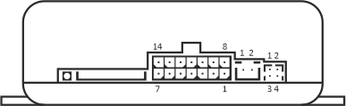
figure 2
|
|
|
| 4-contacts outer button socket signals description |
Table 7 |
|
| Contact № |
Signal name |
Potential in active state |
| 1 |
Ground |
0V |
| 2 |
Indicator-H |
Power |
| 3 |
Contact |
0V |
| 4 |
Indicator-L |
+3.3 V |
|
| 2-contacts thermo-sensor socket signals description |
Table 8 |
|
| Contact № |
Signal name |
Polarity |
| 1 |
Ground |
– |
| 2 |
Sensor |
+ |
|
| 14-contacts socket signals description |
Table 9 |
|
| Contact № |
Signal name |
Polarity |
Wire colour in harness* |
Description |
| 1 |
CAN1-H |
+ |
Brown |
Digital bus CAN 1, line High |
| 2 |
CAN2-H |
+ |
Green |
Digital bus CAN 2, line High |
| 3 |
IN– |
– |
Grey |
Programmable discrete input, negative |
| 4 |
OUT+ |
+ |
White |
Programmable discrete output, positive |
| 5 |
OUT2– |
– |
Blue |
Programmable discrete output, negative |
| 6 |
Power |
+ |
Red |
Permanent battery "+"(12/24 Volts) |
| 7 |
Ground |
– |
Black |
Permanent battery "–" (0 Volts) |
| 8 |
CAN1-L |
+ |
Brown-White |
Digital bus CAN 1, line Low |
| 9 |
CAN2-L |
+ |
Green-Yellow |
Digital bus CAN 2, line Low |
| 10 |
IN+ |
+ |
Orange |
Programmable discrete input, positive |
| 11 |
LIN |
– |
Yellow |
Digital bus LIN (w-bus) |
| 12 |
OUT1– |
– |
White-Blue |
Programmable discrete output, negative |
| 13 |
Power |
+ |
Red |
Permanent battery "+"(12/24 Volts) for powering of conjugated with Therminal modules |
| 14 |
Ground |
– |
Black |
Permanent battery "–"(0 Volts) for powering of conjugated with Therminal modules |
*for universal cable with cut ends
|
| SIM installation |
|
SIM-card in Mini-SIM format is required for GSM-module operation and should be purchased separately from local GSM operator (2G network with GPRS technology
support is demanded).Note: If the operator supports 3G/4G phones only, a SIM-card from the operator can't be used in Therminal.
Some SIM cards (usually ones produced in 2000s) require some preparing operations to be done:
1. Put the SIM-card to a mobile phone and disable PIN-code request on phone reboot (brand new cards are usually supplied with disabled PIN request).
2. Check for SMS-center number is written in SIM-card memory. All up-to-date SIMs are supplied with SMS-center written. The number may absent for old SIM-cards. Put the SIM-card to
a mobile phone, then send SMS to another mobile phone, check for SMS delivery.
Choose tariff plans with non-expensive/pre-paid SMS traffic for control by SMS or with pre-paid mobile data traffic for control via Internet (50-100 Mb per month is enough). Combine phone
account with GSM module account if possible.
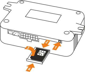
figure 3
Install SIM card into the GSM-module, as shown at the figure 3. The operation should be performed with unplugged power from the GSM-module. Press with a thin blunt object (philips
screwdriver, pen, etc.) on the SIM-holder ejector pushbutton (1), pull for the SIM-holder and pull the holder out of the housing (2) . Then put the SIM into the holder to commit (3)
and insert the holder back to the housing up to the stop (4).
|
|
|
| Troubleshooting |
|
Heater start from the button works independently from GSM-module network status. Use it to check for the heater is in order.
If the heater doesn't start from the button: check all connections, make diagnostics of the heater. In case when the heater starts from the button, but doesn't start via GSM
(SMS, voice call or app) use GSM-module indication for diagnostics: press and hold the button until the embedded LED flashes from 5 to 10 times, then release the button.
GSM-module goes to status indication mode. Status indication mode also becomes active for 2 minutes after boot or restart. See table 10 for details.
|
|
|
| GSM-module indication |
Table 10 |
|
| Number of flashes in series |
GSM-module status |
User action required |
| 1 |
Unknown |
Therminal was armed by the command <password> Alarm on. Status indication in this mode is not available. Disarm Therminal by the command
<password> Alarm off at first.
|
| 2 |
Not available for GSM control |
1. Check for presence of SIM inside the module
2. Check that SIM installed correctly
3. Install SIM into a phone and disable PIN request
4. Check that GSM-module number is active: make a voice call and wait for "busy" tone²
5. Make sure that the GSM-module hasn't went to Shutdown mode by reason of battery discharge
|
| 3 |
Waiting for GSM ready |
GSM-module is loading and temporary not available for GSM control. No user action required.
|
| 4 |
Waiting for GSM registration complete |
GSM-module is temporary not available. Possible reasons: no available networks (no signal, roaming prohibited), SIM locked by the provider. Change button
indication mode to check GSM signal strength level.
|
| 5 |
Ready for command reception |
No user action required.
If the module stopped to send SMS or connect to the server (the app notifies that the vehicle is offline),
check balance of GSM account by using operator service (i.e. web account). Balance request by using module embedded function is not available if balance is inadequate. |
| 6 |
Ready for command reception, roaming mode |
No user action required. |
¹Switch off GSM-module's power supply before the operation
²Heater start may be performed. Make the second voice call to stop the heater
|
|